2026-10-05
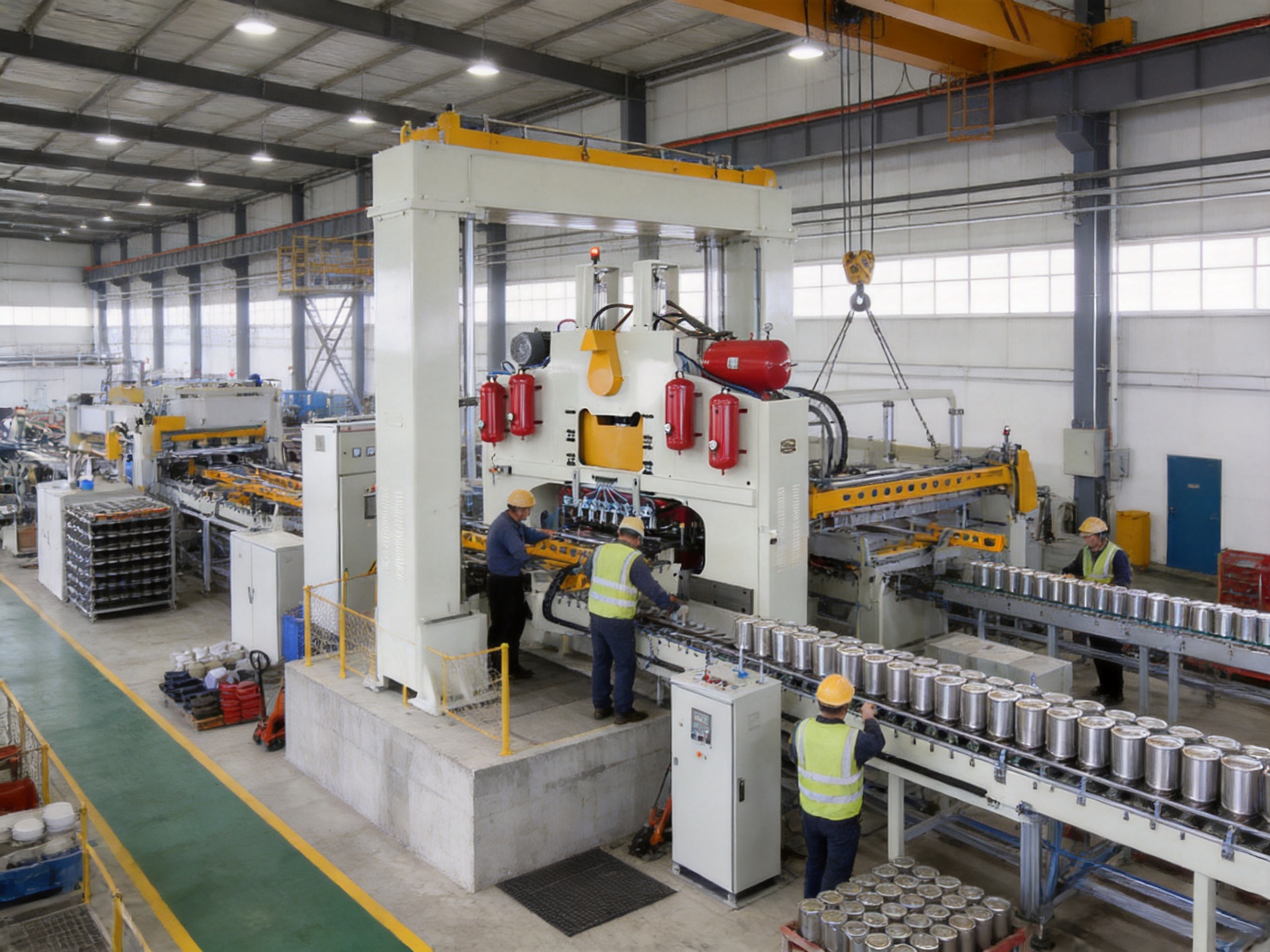
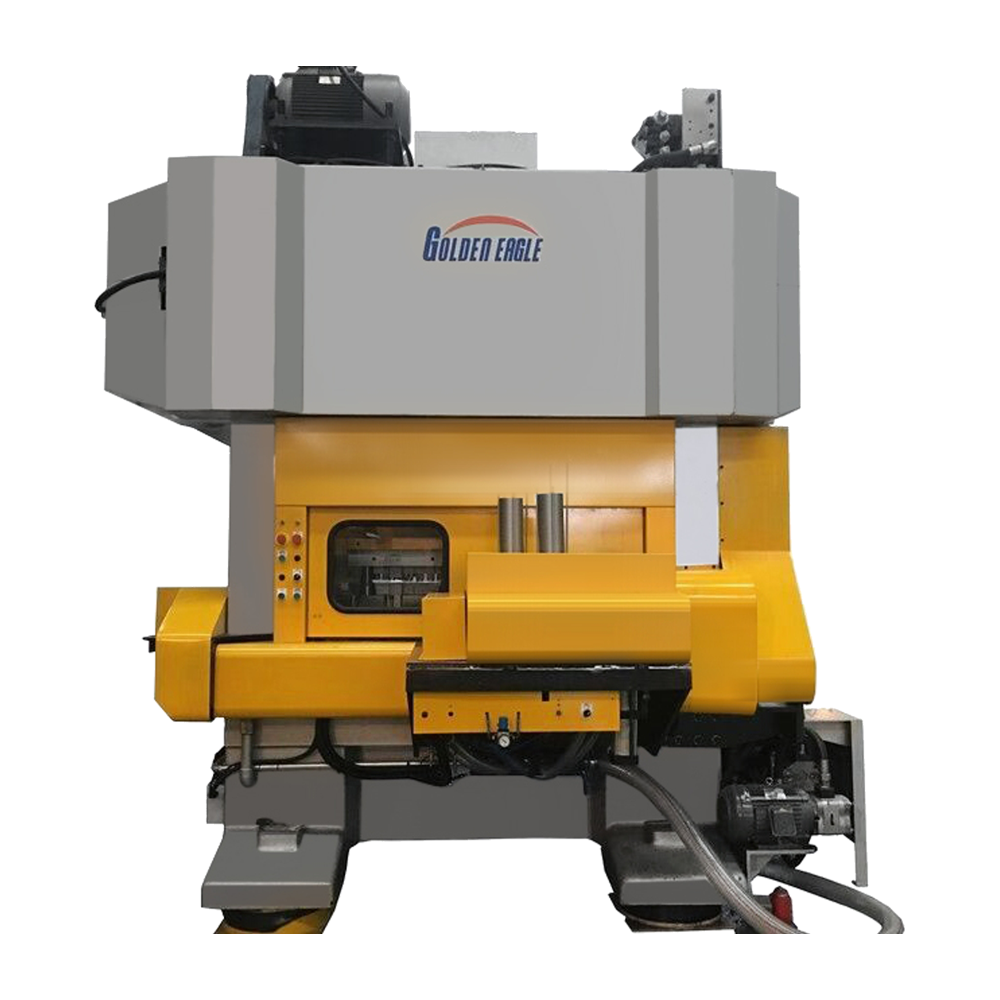
Modern metal packaging production depends on equipment that can combine high output, stable forming quality, rapid die changes, and dependable long-term operation. The CNC Automatic Gantry Press O-Frame Pressing Machine is designed for this demanding environment. It is a high-speed pressing solution for producing metal can ends, bottom covers, base covers, large tank covers, chemical tank covers, and selected screw-cap components.
As part of a complete tin can lid end making system, the machine performs the essential punch-pressing operation that converts prepared tinplate or other suitable metal sheets into accurately formed can-end components. Its automatic operating concept, rigid O-frame structure, configurable die capacity, and broad model range make it suitable for different production volumes and product sizes.
The machine is identified in the supplied product information as the CNC-C series. Depending on the selected configuration, the series offers working pressures from 120 kN to 2,500 kN, strokes from 80 mm to 190 mm, and production speeds reaching up to 200 strokes per minute. Certain models are designed for small and medium can ends, while others are intended for larger covers, chemical tanks, and specialized applications.
With its combination of mechanical strength, automatic feeding compatibility, multi-die capability, and precision manufacturing, this pressing machine provides a practical alternative to less flexible single-purpose presses. It is particularly valuable for manufacturers seeking to expand product variety without installing a completely separate press for every can-end specification.
Can end manufacturing generally involves several coordinated operations. Depending on the final product, the process may include tinplate preparation, sheet coating or printing, blanking, curling, beading, compound lining, scoring, tab forming, embossing, inspection, and packing. The pressing stage is one of the most important operations because it establishes the main geometry of the end component.
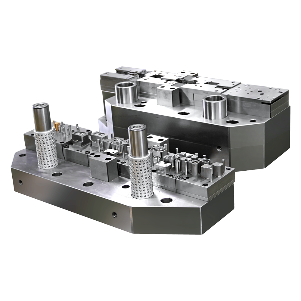
During pressing, a prepared metal blank is positioned within a die set. The upper and lower tooling then apply controlled force to form the blank into the required profile. The tooling may create a shallow end, a reinforced bottom cover, a large chemical tank cover, or another customized shape. The press must therefore provide sufficient force, a controlled stroke, accurate alignment, and repeatable cycling.
The CNC automatic gantry press is designed to operate as a central forming unit within this process. It may be combined with automatic feeding equipment, transfer mechanisms, die assemblies, conveyors, inspection systems, and downstream curling or lining equipment. Because the machine can be configured with different die capacities, it can serve both conventional single-die production and higher-output multi-die production.
For a can manufacturer, the quality of the press directly affects material utilization, dimensional stability, sealing performance, and the smooth operation of later processes. A poorly controlled pressing operation can produce uneven profiles, distortion, incomplete forming, excessive scrap, or difficulty during curling and seaming. A properly selected press helps create consistent components that move reliably through the rest of the line.
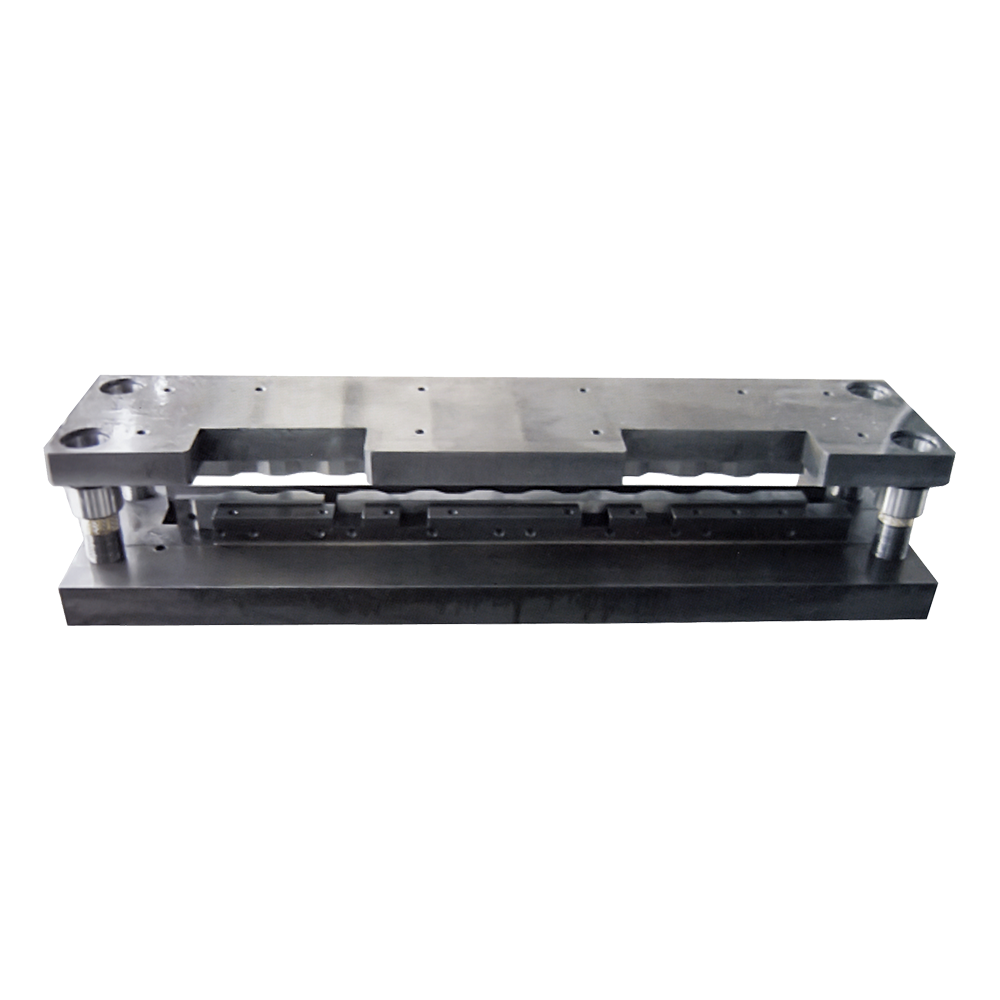
The product is an automatic O-frame pressing machine designed primarily for high-speed metal can-end production. The O-frame, or gantry-style, construction provides a rigid load-bearing structure around the pressing area. This structure helps resist deformation under high working pressure and supports accurate interaction between the press slide, die assembly, and worktable.
The general model designation is CNC-C, with several variants available for different force requirements, working strokes, die capacities, and product applications. The listed models include CNC-C1B, CNC-C1D, CNC-C1W, CNC-C1H, CNC-C2, CNC-C12, CNC-C6, CNC-C6D, CNC-C6W, and CNC-C8.
The supplied information states that the machine can be used for various tailor-made can sizes. This is important because metal packaging producers often manufacture several diameters and profiles rather than a single standardized end. The press can be equipped with tooling appropriate to the required product, subject to engineering confirmation of material, diameter, thickness, forming depth, die arrangement, and production target.
Depending on model and product diameter, the listed operating speeds reach approximately 150 to 200 strokes per minute. The broader product description refers to systems operating at speeds ranging from 150 to 3,000 cycles per minute depending on cap size, but the detailed CNC-C model data specifies up to 200 strokes per minute. Therefore, final output should be calculated from the selected model, number of dies, product size, feeding arrangement, and actual operating conditions.
The press is described as an automatic punch-pressing machine. Automatic operation reduces the need for continuous manual positioning of blanks and helps synchronize the press with feeding, transfer, and collection systems. It also supports more consistent production rhythms, especially when the machine is integrated into a complete can-end line.
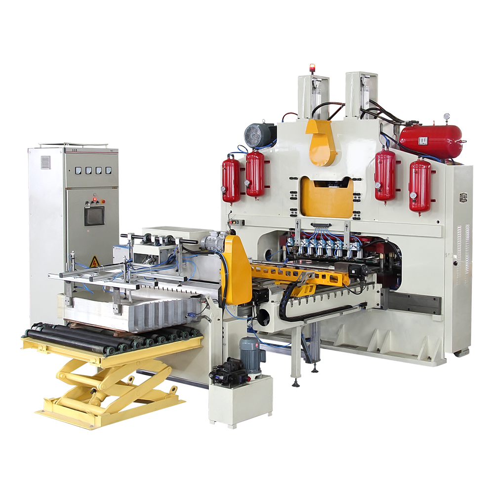
CNC Automatic Gantry Press O-Frame Pressing Machine
The CNC-C family covers a broad range of working pressures. The smaller CNC-C8 is listed with a working pressure of 120 kN, while the CNC-C2 is listed at 450 kN. Several CNC-C1 variants provide 900 kN, the CNC-C6 family provides 1,200 kN, and the heavy-duty CNC-C12 reaches 2,500 kN.
This range allows manufacturers to select a press according to the forming force required by the product. Small covers and lighter components do not necessarily require the same capacity as large tank covers or deeply formed products. Selecting an appropriately sized press can help avoid unnecessary investment in an oversized machine while ensuring that the equipment is not overloaded during production.
High working pressure is especially valuable when the product requires strong embossing, reinforced profiles, deep forming, or larger diameters. The rigid frame and adequately sized drive system must work together to maintain stable forming conditions. A machine with insufficient force may produce incomplete or inconsistent shapes, while a properly specified press provides a larger operating margin.
Stroke specifications in the series range from 80 mm on the CNC-C12 to 190 mm on the CNC-C8. Many of the CNC-C1 and CNC-C6 models use a 105 mm stroke, while the CNC-C1H uses a 140 mm stroke. The CNC-C2 is listed with a 100 mm stroke.
Stroke length influences the available forming travel, die design, cycle characteristics, and suitability for different end profiles. A shorter stroke can be appropriate for certain compact forming operations, while a longer stroke may be needed for larger or more complex products. The availability of multiple stroke configurations makes the series adaptable to a wider range of tooling requirements.
One of the strongest advantages of the machine series is its ability to accommodate multiple dies on selected models. Depending on the model and product diameter, the maximum loading capacity ranges from one die to as many as 15 dies.
For example, the CNC-C1B and CNC-C12 are listed with capacity for up to 15 dies in certain configurations. The CNC-C1D and CNC-C1W can accommodate up to seven dies for specified smaller diameters, while the CNC-C6, CNC-C6D, and CNC-C6W can accommodate up to eight dies for the same general diameter range. Other models are intended for one or two dies.
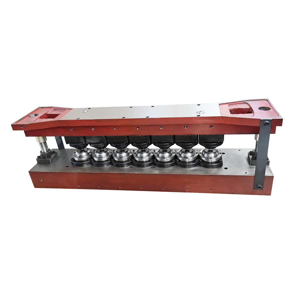
Multi-die operation can significantly increase productivity because several components may be formed during each press cycle. It also helps manufacturers use one press for multiple lanes or product positions. The exact output depends on die layout, blank arrangement, feeding speed, product dimensions, metal properties, and the number of effective forming stations.
For larger products, the number of dies is naturally reduced. The supplied specifications indicate configurations ranging from one to 15 dies for approximately 52–99 mm products and from one to 15 dies for approximately 153 mm products, depending on the selected machine. These values should be treated as model-specific maximum loading references rather than a universal production guarantee.
Most of the larger models are listed with a maximum plate width of 1,150 × 1,150 mm. The CNC-C8 is listed with a 1,000 × 1,000 mm plate. A generously sized worktable provides room for multiple die positions, larger tooling, and more flexible layout planning.
A large plate is useful for manufacturers that require multi-lane production or must accommodate larger can-end tooling. It can also simplify future product expansion because the press may have sufficient working area for additional die arrangements, provided that the total load and machine configuration remain within engineering limits.
Automatic operation is a major benefit in high-volume metal packaging. Once the press, die system, feeding mechanism, and safety controls have been properly set, the equipment can maintain a repeatable production rhythm with limited manual intervention. This reduces the physical workload for operators and helps standardize the handling of blanks.
Automatic feeding also minimizes variations caused by inconsistent manual placement. Accurate positioning is essential because an offset blank can lead to uneven forming, die damage, material waste, or a defective finished end. When integrated with suitable feeding equipment, the press supports a more controlled and predictable production process.
The CNC-C family includes machines with different capacities and intended uses. The following table summarizes the principal specifications supplied for the available models. Actual production capability depends on tooling, material, product geometry, and final technical confirmation.
| Model | Working Pressure | Stroke | Maximum Listed Speed | Main Power | Total Power | Host Weight |
|---|---|---|---|---|---|---|
| CNC-C1B | 900 kN | 105 mm | Up to 200 spm | 7.5 kW | 25 kW | 11.8 t |
| CNC-C1D | 900 kN | 105 mm | Up to 180 spm for selected small diameters | 7.5 kW | 25 kW | 11.8 t |
| CNC-C1W | 900 kN | 105 mm | Up to 180 spm for selected small diameters | 7.5 kW | 25 kW | 11.8 t |
| CNC-C1H | 900 kN | 140 mm | Up to 180 spm for selected small diameters | 11 kW | 30 kW | 11.8 t |
| CNC-C2 | 450 kN | 100 mm | Up to 200 spm | 5.5 kW | 20 kW | 10 t |
| CNC-C12 | 2,500 kN | 80 mm | Up to 200 spm | 22 kW | 35 kW | 30 t |
| CNC-C6 | 1,200 kN | 105 mm | Up to 180 spm for selected small diameters | 15 kW | 32 kW | 12 t |
| CNC-C6D | 1,200 kN | 105 mm | Up to 180 spm for selected small diameters | 15 kW | 32 kW | 12 t |
| CNC-C6W | 1,200 kN | 105 mm | Up to 180 spm for selected small diameters | 7.5 kW | 35 kW | 12.2 t |
| CNC-C8 | 120 kN | 190 mm | Up to 200 spm | 4 kW | 18 kW | 6.5 t |
The CNC-C1B is a 900 kN model with a 105 mm stroke and a listed maximum speed of up to 200 strokes per minute. It can support up to 15 dies for certain 52–99 mm products and up to six dies for a larger approximately 153 mm configuration. Its stated function is mainly the production of bottom covers and base covers.
This model is suitable for manufacturers seeking a balance between high throughput, substantial force, and multi-die capability. Its 1,150 × 1,150 mm plate provides considerable space for a production-oriented tooling arrangement.
The CNC-C1D and CNC-C1W share several principal specifications, including 900 kN working pressure, a 105 mm stroke, and a host weight of approximately 11.8 tonnes. Their listed speed is up to 180 strokes per minute for selected 52–99 mm products and approximately 150 strokes per minute for a 153 mm product configuration.
Both models are listed with capacity for up to seven dies in the smaller diameter range and up to two dies in the larger range. The descriptions identify them with bottom-cover and base-cover applications, including configurations described as “two empty,” which may refer to a particular transfer, cavity, or production arrangement. The exact meaning should be confirmed in the machine layout and technical proposal before ordering.
The CNC-C1H is also rated at 900 kN, but it uses a longer 140 mm stroke and an 11 kW main motor. It is identified for large tank covers and chemical tank covers, with a two-level transmission arrangement. The listed die capacity is one die for the smaller stated diameter range and one die for the larger approximately 153 mm range.
This configuration demonstrates how the series can be adapted beyond conventional food-can ends. Chemical tank covers and large covers often require different forming travel, tooling dimensions, and handling methods. A dedicated model with an appropriate stroke and drive system can provide a better fit than attempting to use a small-cover press for a larger application.
The CNC-C2 offers 450 kN working pressure, a 100 mm stroke, and a listed speed of up to 200 strokes per minute. It is lighter than the 900 kN models, with a stated host weight of approximately 10 tonnes and total power of 20 kW.
Its die capacity is listed as up to two dies for the smaller diameter range and up to one die for the larger range. This makes it a practical option for applications requiring moderate forming force, compact multi-die capability, and a lower equipment scale than the high-capacity models.
The CNC-C12 is the heavy-duty model in the listed range. It provides 2,500 kN working pressure, an 80 mm stroke, a 22 kW main motor, and 35 kW total power. With an approximate host weight of 30 tonnes, it is intended for demanding forming operations.
The model is listed with up to 15 dies for both the smaller and larger referenced product arrangements. Its description identifies it primarily with bottom-cover and base-cover production and a double-row die arrangement without air. Its high force capacity may be advantageous for high-strength materials, larger profiles, or forming applications that require substantial pressure and rigid support.
The CNC-C6 family provides 1,200 kN working pressure and a 105 mm stroke. The CNC-C6, CNC-C6D, and CNC-C6W are listed with up to eight dies for selected small diameters. For the larger approximately 153 mm configuration, the CNC-C6 and CNC-C6D are listed with up to three dies, while the CNC-C6W is also described with a three-die arrangement in the supplied data.
These models are aimed mainly at bottom-cover and base-cover production. The C6D and C6W descriptions include a two-empty arrangement, indicating a specialized production or transfer configuration. Model selection should be based on the desired product layout, blank feeding direction, tooling arrangement, and whether the line requires specific empty or transfer positions.
The CNC-C8 is the most compact model in the listed series, with 120 kN working pressure, a 190 mm stroke, and a 1,000 × 1,000 mm maximum plate. It has a stated host weight of approximately 6.5 tonnes and total power of 18 kW.
The model is identified mainly for the production of four-screw caps. Its longer stroke and smaller working pressure distinguish it from the larger bottom-cover and tank-cover models. For a manufacturer producing specialized screw-cap components, the CNC-C8 may provide a more appropriate configuration than a larger press designed for heavier forming work.
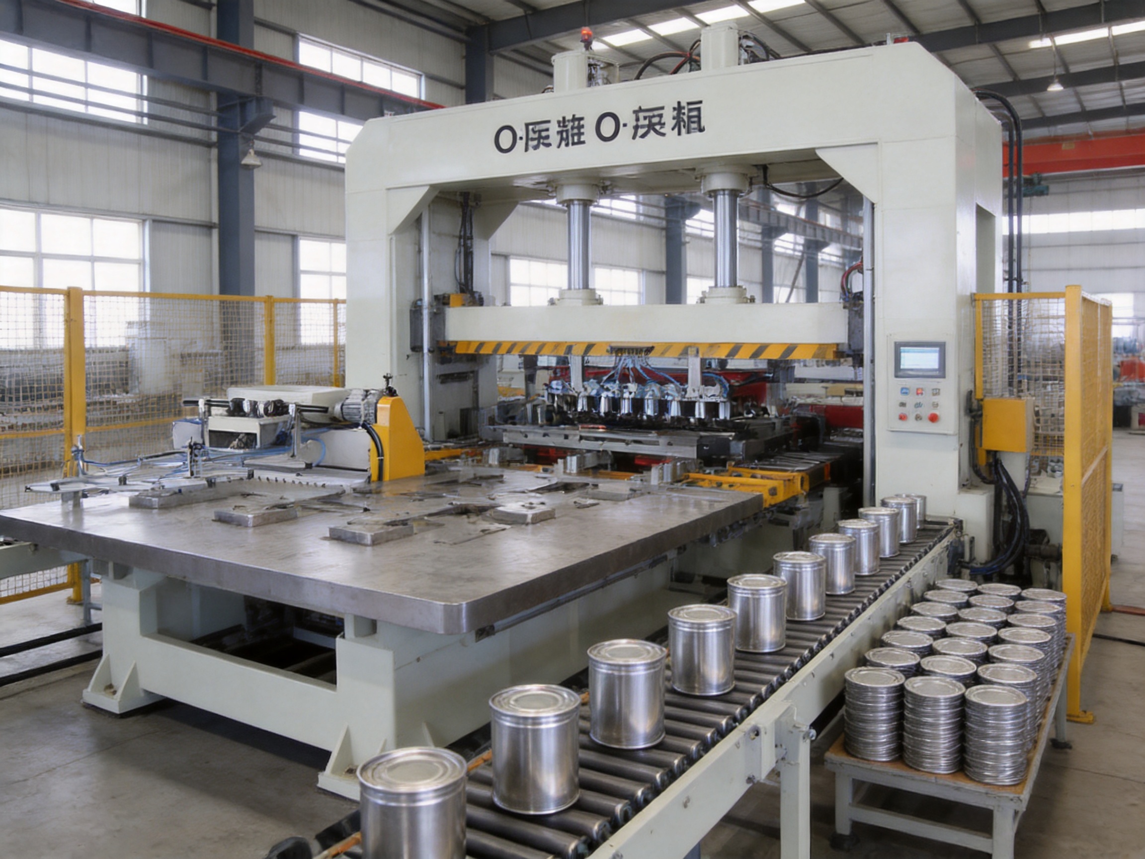
A conventional single-purpose press may be optimized for one product diameter, one die arrangement, or one type of cover. That approach can be effective for very high-volume production of a single item, but it may become limiting when customer orders change or when a packaging manufacturer needs to produce several sizes.
The CNC-C series offers multiple models and die capacities. This gives users more options when matching equipment to small can ends, large covers, chemical tank covers, bottom covers, base covers, and screw-cap components. The tailor-made can-size concept also supports engineering adaptation for specific product requirements.
Multi-die capability can provide a substantial productivity advantage over single-die operation. Several blanks can be processed during one cycle, allowing the press to make better use of its available stroke and working area. For large-volume producers, this may reduce the number of presses needed for a target output.
Multi-die production also creates opportunities for line balancing. The press can be selected according to the required number of lanes, while upstream feeding and downstream operations can be designed to match the actual press capacity. This is particularly useful when the machine is part of an integrated can-end production line rather than operating as an isolated unit.
The O-frame structure provides a closed load path around the working area. Under pressing force, a rigid frame helps maintain the relationship between the upper tooling, lower tooling, and worktable. This can contribute to stable forming accuracy and reduce the risk of frame deflection compared with less rigid structural arrangements.
Frame rigidity is especially important for multi-die tooling. When multiple cavities operate across a large plate, consistent force distribution and alignment are necessary to reduce variation between positions. The actual performance depends on structural design, machining accuracy, die quality, setup, and maintenance, but the O-frame concept provides a strong foundation for precision pressing.
The range from 120 kN to 2,500 kN allows users to select a machine based on the actual forming requirement. This is more economical and technically appropriate than using one oversized press for every product. A manufacturer can choose a smaller model for specialized screw caps, a mid-range model for conventional ends, or a heavy-duty model for large and demanding covers.
Automatic operation and feeding compatibility can reduce manual handling and improve production consistency. Compared with manually loaded presses, an automatic line can offer more stable blank positioning, improved operator safety, and better utilization of labor. It also supports more systematic monitoring of production speed, stoppages, quality defects, and maintenance events.
Can-end production is not identical across all factories. Different materials, diameters, profiles, coatings, scoring requirements, and sealing designs may require different die structures and operating parameters. The CNC-C series is presented as a tailor-made solution for various can sizes. This engineering approach allows the press and tooling to be considered together rather than treating the machine as an inflexible standard unit.
The manufacturer, Zhejiang Golden Eagle Food Machinery Co., Ltd., has a long history in can-making machinery and mold production. The company was established in 1978 and is located in Zhoushan, Zhejiang Province, China. Its background includes the production of can-making machinery, can-making molds, and complete equipment lines for different metal packaging applications.
The company reports a workforce of more than 350 trained personnel, including experienced design and development engineers. This combination of mechanical manufacturing experience and engineering resources is important for complex press projects because the machine, die, feeding system, transfer components, and downstream equipment must operate as one coordinated system.
The company states that it uses CNC high-precision machining equipment together with complete mechanical machining equipment. Precision machining is particularly important for press components, die holders, guide elements, working plates, shafts, and other parts whose dimensional accuracy affects alignment and repeatability.
Modern CNC manufacturing can improve consistency from one component to another by using controlled tool paths, repeatable setups, and digital inspection procedures. For a pressing machine, this supports closer control of critical interfaces and helps reduce variation during assembly and maintenance.
Many press suppliers manufacture the machine while separate tooling companies design and make the dies. The manufacturer described here has experience in both can-making machinery and can-making molds. This integrated knowledge can simplify the engineering relationship between the press and the forming tool.
Tooling affects nearly every aspect of production: force demand, stroke requirement, blank positioning, product geometry, material flow, die life, and production speed. A supplier familiar with both the press and the mold can evaluate these factors together. This can reduce communication gaps during project design and commissioning.
The company reports that its product designs are similar in principle to equipment associated with major international can-making machinery brands, while also incorporating experience gained through practical production. This statement should be understood as an engineering reference rather than a claim that the machines are identical to equipment from other manufacturers.
Practical production experience is valuable because a press must perform reliably under real factory conditions, not only meet theoretical design specifications. Long production runs expose issues related to lubrication, vibration, die wear, blank handling, alignment, electrical control, and maintenance access. Continuous improvement based on field experience can help address these operational requirements.
The company reports certification to the ISO 9001 quality management system and ISO 14001 environmental management system. ISO 9001 provides a structured framework for quality processes, documentation, corrective action, and continual improvement. ISO 14001 addresses environmental management practices and organizational control of environmental impacts.
Certification does not replace product inspection or customer acceptance testing, but it demonstrates that the manufacturer has established formal management processes. For international buyers, documented quality and environmental systems can provide additional confidence during supplier evaluation.
The company reports that it has produced more than 10,000 pieces of can and can-lid equipment. Its equipment has been supplied to can manufacturers and canning factories in Europe, Asia, Africa, North America, South America, and Oceania.
International installation experience can be valuable when a machine must be adapted to different electrical standards, factory layouts, operator practices, documentation requirements, and production materials. It may also help the supplier understand the importance of remote technical support, spare-parts planning, commissioning, and training.
Most of the larger CNC-C models are listed with installation dimensions of approximately 8,000 × 6,310 × 3,170 mm. The CNC-C12 shares this general footprint, while the CNC-C8 is listed at approximately 5,400 × 4,000 × 2,500 mm. These dimensions indicate that the press is substantial industrial equipment and must be planned as part of a suitable production facility.
Before installation, the buyer should confirm the actual machine outline, service clearances, feeder position, control cabinet location, die storage area, material flow direction, and maintenance access. The listed installation dimensions may represent the primary machine and associated working envelope, but the final layout should include space for operators, tooling changes, inspection, lubrication, safety barriers, and material movement.
Foundation requirements must also be reviewed. Models weighing from approximately 6.5 tonnes to 30 tonnes may require a reinforced foundation designed for static load, dynamic load, vibration, and leveling. The supplier should provide foundation drawings, anchor details, allowable floor loading, and installation instructions before civil work begins.
Electrical planning is equally important. Main power ratings range from 4 kW to 22 kW, while total power ratings range from 18 kW to 35 kW in the listed models. The factory must provide the correct voltage, frequency, protection devices, grounding, cable capacity, and control-panel environment. Additional equipment such as feeders, conveyors, compressors, lubrication systems, and inspection devices may increase the total line demand.
Ventilation, lighting, noise control, and safe access should be included in the factory plan. Operators must be able to reach the control system and inspection points without entering hazardous zones. Maintenance personnel need sufficient clearance to remove tooling, inspect drive components, replenish lubricants, and replace wear parts.
The pressing machine cannot be evaluated separately from the die set. The correct die design depends on can-end diameter, metal thickness, temper, coating, forming depth, bead or embossment profile, scoring requirements, and required sealing characteristics.
When ordering, the buyer should provide accurate product drawings and material specifications. Important data may include blank diameter, finished outside diameter, internal profile, countersink depth, embossing design, score line location, material grade, thickness tolerance, coating type, and expected production rate.
Die capacity should not be selected solely by counting available positions. The buyer must confirm the total forming force, load distribution, die pitch, blank spacing, feeding direction, and transfer timing. A press capable of holding many dies may still require a reduced number of active stations for a large or deep product.
Tooling materials and surface treatments also influence performance. Wear-resistant components can help extend service life, while carefully controlled clearances reduce burrs, scratches, and deformation. Periodic die inspection is essential because wear can gradually affect product dimensions even when the press itself remains correctly adjusted.
Consistent can-end production requires more than high speed. Quality control should cover incoming metal, blank dimensions, die condition, press alignment, operating force, stroke, product geometry, surface condition, and final inspection.
During commissioning, the press should be tested at gradual speed increases. Initial trials should confirm safe operation, blank transfer, die clearance, lubrication, emergency stops, guarding, and product quality. After stable operation is achieved, the line can be optimized for target speed and output.
Manufacturers should establish inspection procedures for critical dimensions. These may include overall diameter, countersink depth, profile height, flange geometry, embossment depth, and scoring position. Visual inspection should check for scratches, cracks, wrinkles, incomplete forming, excessive burrs, and coating damage.
Statistical process control can help identify gradual drift before it becomes a major quality problem. Measurements from different die positions should be compared because variation may occur between cavities. If one position begins producing a different profile, possible causes include uneven wear, misalignment, material variation, or an issue with the die assembly.
Scrap monitoring is another important indicator. A sudden increase in rejects may result from incorrect blank positioning, feeding instability, die damage, lubrication problems, or a change in material properties. Recording the defect type and time of occurrence helps maintenance and production teams identify the root cause.
Preventive maintenance is essential for any high-speed press. The maintenance plan should follow the supplier’s recommended schedule and include lubrication, fastener inspection, alignment checks, electrical inspection, safety-system testing, and wear-part replacement.
Lubrication must be appropriate for the machine’s bearings, guides, drive components, and operating conditions. Insufficient lubrication can increase friction and wear, while incorrect or excessive lubrication may contaminate components or attract metal particles. Operators should record lubrication activities and report abnormal noise, heat, vibration, or leakage.
Die maintenance should include cleaning, inspection of cutting and forming surfaces, measurement of critical clearances, and timely replacement of worn inserts. Keeping spare die components available can reduce production downtime. The press itself should not be used to compensate for a worn or incorrectly adjusted die.
Electrical and control systems should be checked regularly. Sensors, limit switches, emergency-stop devices, protective interlocks, and control-panel cooling systems must remain functional. A machine operating at high speed should never be run with a bypassed safety device or an unresolved control fault.
Planned shutdowns provide an opportunity to inspect the frame, fasteners, drive system, worktable, and feeding mechanism. Maintenance teams should compare measured conditions with the original installation records. Early detection of looseness, misalignment, or abnormal wear can prevent more serious damage.
A metal forming press contains moving parts and stores significant mechanical energy. Safe operation requires appropriate guarding, interlocks, emergency stops, lockout procedures, operator training, and clear work instructions.
Operators should be trained in normal operation, setup, product inspection, jam clearing, die change procedures, and emergency response. No person should place hands inside the die area while the press is energized or capable of cycling. Lockout and verification procedures must be applied before maintenance or tooling work.
Tool changes require special attention because dies may be heavy and difficult to handle manually. Suitable lifting devices, certified slings, die carts, and clear communication procedures should be used. The machine area should remain clean and free from loose blanks, oil accumulation, and obstructions.
Noise and metal edges are additional workplace hazards. Appropriate hearing protection, safety footwear, eye protection, and gloves for material handling should be selected according to the factory risk assessment. Gloves should not be worn near exposed rotating or feeding components if they could become entangled.
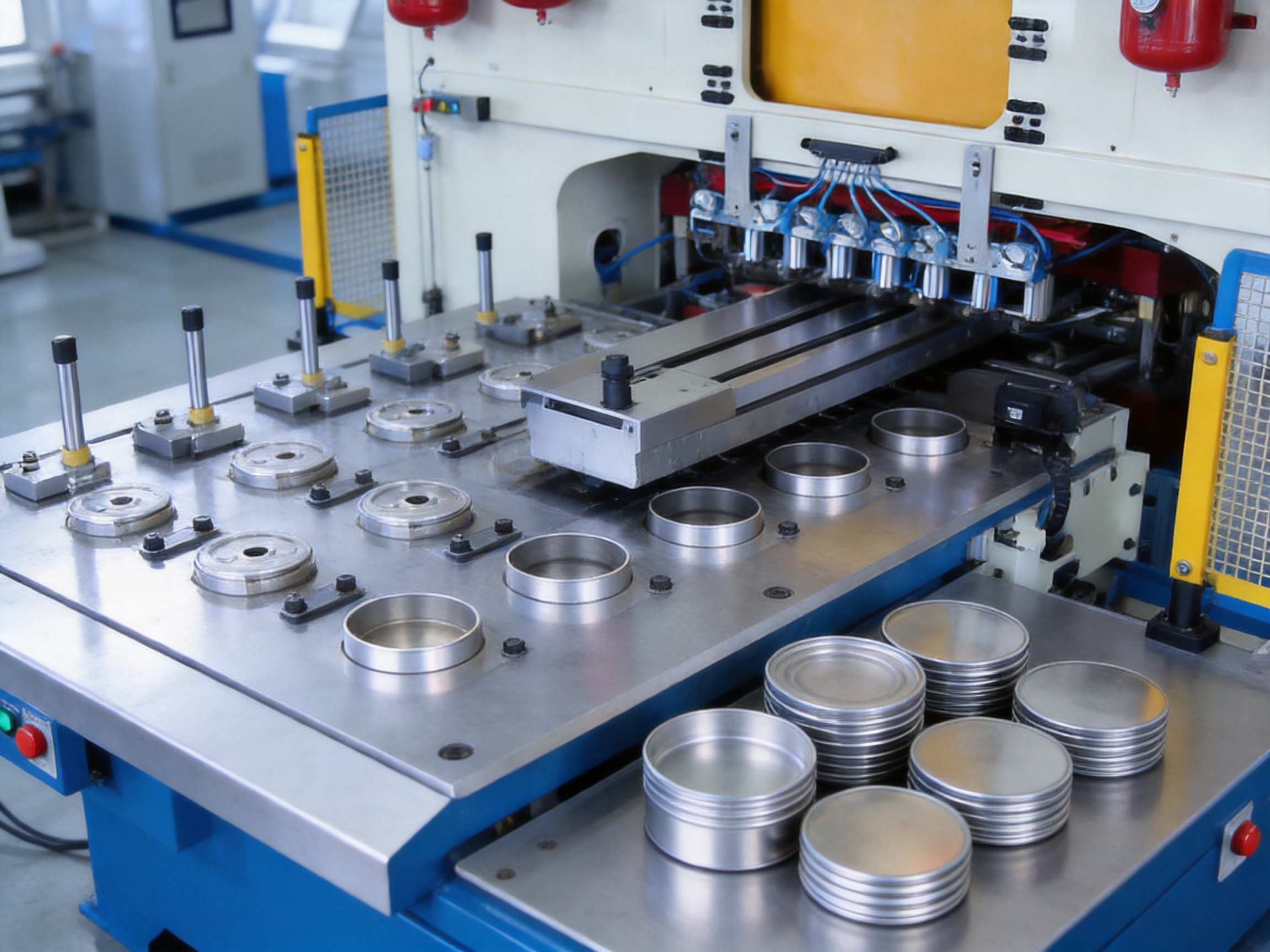
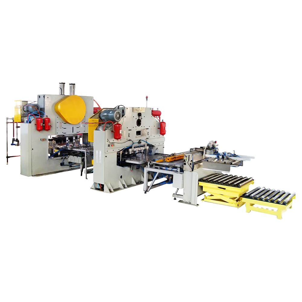
The pressing machine can serve as one unit within a broader tinplate can production line. Depending on the product, upstream equipment may include sheet feeding, slitting, coating, printing, blanking, and automatic stack handling. Downstream equipment may include curling, lining, scoring, tab forming, beading, inspection, counting, and packing.
The press can also be coordinated with automatic feeding machines. A well-designed feeder must match the press cycle, blank dimensions, die layout, and permissible positioning tolerance. The interface between the feeder and press should be confirmed during the design stage, including signal exchange, mechanical height, transfer timing, sensors, and emergency-stop circuits.
For complete can-end production, line balance is essential. If the press produces more components than the curling or lining equipment can process, intermediate accumulation may be required. Conversely, a slow downstream machine can reduce the effective utilization of a high-speed press. Production planning should therefore consider the capacity of every connected process.
The manufacturer’s product range includes food-can production lines, beverage-can production lines, can-lid production lines, chemical tank production lines, aerosol canister production lines, two-piece can production lines, and pop-can production lines. This broad product background can be useful when customers require more than a standalone press.
A successful press installation depends on more than equipment delivery. The supplier reports that it provides installation, commissioning, technical guidance, operation training, and spare-parts support. These services can help the buyer move from factory installation to stable production more efficiently.
Installation support may include machine positioning, leveling, anchoring, connection of utilities, feeder alignment, die installation, safety inspection, and initial dry-cycle testing. Commissioning should proceed from no-load operation to low-speed production and then to the agreed operating conditions.
Operator training should cover startup, shutdown, production adjustment, product inspection, alarm handling, routine cleaning, lubrication, and safe response to jams. Maintenance training should cover wear-part identification, inspection intervals, fault reporting, and spare-parts replacement.
Spare-parts planning is particularly important for export customers. Recommended spares may include sensors, seals, electrical components, lubrication parts, fasteners, wear plates, guide elements, and selected die components. Holding critical spares locally can reduce downtime while replacement parts are being shipped.
Documentation should include operating instructions, electrical diagrams, lubrication charts, foundation drawings, spare-parts lists, safety information, and recommended maintenance schedules. Clear documentation supports consistent operation when the machine is used by different shifts or maintained by different technicians.
The correct model should be chosen through a structured technical review rather than by speed alone. The first consideration is the product. The buyer should identify the can-end diameter, profile, material, thickness, forming depth, and final application.
The second consideration is required output. Expected production should be expressed in finished pieces per minute or per hour, not only in press strokes per minute. If a press uses several dies per cycle, the relationship between stroke rate and piece output must be calculated carefully. Allowance should also be made for setup, cleaning, inspection, material changes, and planned downtime.
The third consideration is forming force. The selected working pressure must provide sufficient capacity for the product and die arrangement. A technical calculation should consider material strength, thickness, blank diameter, forming depth, friction, embossing, and safety margin.
The fourth consideration is tooling capacity. If the production plan includes several products, the buyer should confirm whether the press can accept the necessary die sets and whether die changes can be completed efficiently. Multi-die capability is valuable, but only if it corresponds to the intended product sizes and layout.
The fifth consideration is factory infrastructure. The buyer must verify floor space, foundation, electrical capacity, handling equipment, environmental conditions, and material flow. The heaviest models require careful logistics planning from the unloading point to the final installation position.
The final consideration is lifecycle support. A machine with suitable performance should also have accessible spare parts, clear maintenance requirements, responsive technical support, and a realistic training plan. These factors influence total operating cost throughout the equipment’s service life.
Before requesting a final quotation, a buyer should prepare product drawings, material specifications, expected production volume, required automation level, available factory utilities, and preferred delivery schedule.
The buyer should request confirmation of the following points:
1. Recommended model for each can-end size and material.
2. Guaranteed or expected production speed under the proposed die configuration.
3. Number of active dies and expected output per stroke.
4. Working pressure and estimated forming-force requirement.
5. Stroke, closed height, plate dimensions, and adjustment range.
6. Automatic feeder design and interface requirements.
7. Machine footprint, foundation drawing, and shipping weight.
8. Electrical voltage, frequency, total connected load, and control requirements.
9. Tooling scope, die materials, spare components, and changeover method.
10. Installation, commissioning, training, warranty, and after-sales service.
11. Recommended preventive-maintenance schedule.
12. Acceptance-test procedure and quality criteria for trial production.
Providing complete information at the beginning of the project allows the supplier to recommend a more accurate model and reduces the risk of changes after manufacturing has started.
The machine is mainly designed for metal can ends, bottom covers, and base covers. Depending on the model and tooling, it can also be used for large tank covers, chemical tank covers, and selected four-screw-cap applications. Final suitability depends on product drawings, material, thickness, and forming requirements.
The detailed CNC-C specifications list speeds up to approximately 200 strokes per minute, with certain configurations listed at 180 or 150 strokes per minute for specific product diameters. Actual output depends on the model, die count, product size, feeding system, material, and operating conditions.
Yes. Selected models can accommodate multiple dies. The listed maximum ranges from one die to as many as 15 dies, depending on the model and product diameter. The actual number should be confirmed through a die-layout and load calculation.
The CNC-C1H is specifically described for large tank covers and chemical tank covers. It has a 900 kN working pressure, a 140 mm stroke, and a two-level transmission arrangement. Larger or more demanding products may require another model after technical review.
The CNC-C12 is the highest-capacity model listed in the supplied information. It provides 2,500 kN working pressure, an 80 mm stroke, and an approximate host weight of 30 tonnes.
The CNC-C8 is the most compact listed model. It has 120 kN working pressure, a 190 mm stroke, and an approximate host weight of 6.5 tonnes. It is mainly described for four-screw-cap production.
Yes. The product information describes can sizes as various and tailor-made. However, customization must be confirmed through product drawings, material data, die design, press capacity, and the desired output.
The buyer should provide product drawings, material type and thickness, blank dimensions, target output, desired automation level, number of products, factory power conditions, and any special requirements for embossing, scoring, curling, lining, or inspection.
The company states that it provides installation, commissioning, technical guidance, operation training, and spare-parts support. The exact scope, duration, travel arrangements, and responsibilities should be included in the commercial and technical agreement.
The CNC-C series offers a broader range of working pressures, multiple model configurations, automatic operation, and multi-die options. These features can improve flexibility and productivity. A single-die machine may still be suitable for a simple, dedicated product, so the best choice depends on production volume, product variety, and investment priorities.
The buyer should verify the foundation, floor loading, machine clearance, lifting route, electrical supply, grounding, lighting, ventilation, safety barriers, feeder location, die-handling equipment, and maintenance access. The supplier’s final installation drawings should be used for construction and layout planning.
The CNC Automatic Gantry Press O-Frame Pressing Machine is a flexible and industrially oriented solution for high-speed metal can-end production. Its CNC-C model family covers a wide range of working pressures, strokes, die capacities, dimensions, and application requirements. This enables manufacturers to select equipment for conventional bottom covers, base covers, large tank covers, chemical tank covers, and specialized screw-cap products.
The machine’s key advantages include automatic operation, rigid O-frame construction, multi-die capability, tailor-made can-size support, broad model selection, and compatibility with complete can-making production lines. Compared with a basic single-purpose press, it can offer greater flexibility for manufacturers that produce several products or plan to expand their packaging range.
The manufacturer strengthens the product proposition through long-term experience in can-making machinery and molds, CNC precision machining, integrated tooling knowledge, international project experience, ISO 9001 and ISO 14001 management systems, and reported production of more than 10,000 pieces of can and can-lid equipment.
For the best result, the machine should be selected as part of a complete technical plan. Product drawings, material specifications, output targets, die arrangements, feeding systems, factory infrastructure, safety requirements, and after-sales support must all be evaluated together. When correctly specified and maintained, the press can provide a reliable foundation for efficient, repeatable, and scalable metal can-end manufacturing.
1. Product technical information for the CNC-C automatic gantry O-frame pressing machine, including model specifications, working pressure, stroke, speed, die capacity, power, weight, dimensions, and application descriptions.
2. Company profile and manufacturing information for Zhejiang Golden Eagle Food Machinery Co., Ltd., including company history, production experience, CNC machining capability, management-system certifications, and service scope.
3. General principles of metal forming and mechanical press operation for tinplate can-end manufacturing.
4. ISO 9001 quality management system principles applied to industrial machinery manufacturing.
5. ISO 14001 environmental management system principles applied to machinery production and factory operations.
Related Products

Founded in 1978, the company is one of the largest can-making machinery well-known companies at home and abroad.
Product Categories
Contact Information
Zhongshatou Shenjiamen Zhoushan Zhejiang China
+86-580-3056646

 English
 中文简体
 русский
 عربى
 Español